Acoustic loss at substantial ultrasonic strain
in
6Al-6V-2Sn and
sintered
6Al-4V titanium
David Wuchinich[1]
ã David
Wuchinich 2004
Keywords: Q, attenuation, dissipation, fatigue, titanium,
ultrasonic, sintered, powdered metal, stress
PACS code:
74.75.Ld
Abstract
The mechanical Q of the high
strength 6Al-6V-2Sn titanium alloy and of two alloys of sintered 6Al-4V is
measured and compared with values obtained for standard cast and rolled 6Al-4V
at 20 kHz cyclic strains ranging for 0.18 to 0.42 percent. 6-6-2 was found to exhibit comparable loss
to the standard samples while the sintered specimens revealed much lower
dissipation. Annealing of one of the
sintered samples reduced the Q to those found typical for cast and rolled
material. The 6-6-2 material survived
continuous operation at strains in the neighborhood of 0.4 percent. It appears that sintering may provide an
economical process for making ultrasonic horns and that intensities greater
than can typically be produced by use of 6-4 Ti may be available using 6-6-2Ti.
Introduction
Mechanical dissipation
resulting from hysteresis in the stress-stain relationship in many metals has
been studied extensively in relation to fatigue and the operational life of
components subjected to cyclic stress at ultrasonic frequencies because this
loss limits the maximum excursion that can reliably be produced[2]. As the alloy 6Al-4V titanium is used
extensively in ultrasonic welding and surgical horns, and is often subjected to
strains in the range of 0.25 percent during operation, Mason’s exemplary method
and comprehensive studies have provided a guide for fatigue -safe design for
this alloy[3].
A complete treatise of his methods has also been published[4]. Additional studies of similar alloys have
produced comparable results[5]: The mechanical Q is constant for strains up
to 0.25 percent, thereafter decreasing rapidly. In this respect, this alloy of titanium is distinguished among
other metals employed as horns, such as steel and aluminum, both of which exhibit
progressively greater loss with increasing strain[6]. A strain of 0.25 percent corresponds to a
stress of 276 Mpa (40 kpsi) and it is this value that has been adopted as the
practical endurance limit for titanium horns operating at ultrasonic frequencies.
Horns and ultrasonic
surgical tips have commonly been made by machining rolled stock taken from
castings. Recently, sintered versions
of the alloy have become available[7]
and offer substantial economies in the manufacture of large quantities of
identical items as the process results in horns having near to net finished
shape from molds. Sintering, however,
may result in porosity which, if occurring in regions subject to substantial
strain, can cause stress concentrations that precipitate failure. Hence, an acoustic evaluation of this
material’s tolerance of large strains is of interest.
Also of interest in this
study is the performance of the titanium alloy 6Al-6V-2Sn, known for having
higher strength than 6Al-4V and which has become available to users in common
rolled bar form in less than mill run quantities.
Theory
The half wavelength
resonator utilized by Mason and which closely resembles in action the classical
model of simple harmonic vibration utilizing two opposing and equal masses
connected by a mass-less spring is a simple candidate for evaluation of
acoustic loss. A schematic
representation of the structure is shown in Figure 1.
Figure 1 Test specimen geometry
This model is chosen for two
principal reasons: (1) stress is
confined to the spindle portion of the resonator and is substantially uniform
in this region and (2) the abrupt transistion in cross sectional area between
the mass and spring elements permit the production of large cyclic stress for
modest and easily produced free end amplitude excursions. As elastic loss is often a function of the
peak stress level, confinement and uniformity of stress permits a reliable
measurement of loss. Production of
stress levels likely to reveal substantial losses without resort to excitation
by high intensity transducer and horn amplifiers is also an advantage.
Exact and finite element
analysis reveal that indeed, for the first extensional resonant mode, the end
sections with the larger diameter move uniformly in opposite directions and
that the slender center section is subjected to substantially uniform strain
with a frequency approximately given by
 (1)
(1)
with E representing
Young’s modulus.
The stored energy of
vibration, Es, can be computed as:
 (2)
(2)
where s is the peak stress and V the volume. As the stress is principally located within
the slender stem of length l whose cross section, A, is constant, Eq.
(2) becomes:
 .
(3)
.
(3)
V = Al, the
volume of the spindle. The exact value
can be computed from finite element modal analysis or from solutions for the
wave equation for a model consisting of connected and appropriately sized
prismatic steps[8] , but Eq.
(3) is sufficiently accurate for computations within fifteen percent of the
true value if the geometry is chosen so that the stress is predominantly
present in the stem.
The stress can be computed
from optical measurements of the displacement of the end mass using, for
example, a microscope with a calibrated reticule as:
![]() (4)
(4)
where d is the excursion (peak to peak motion of either end
mass) and l is the length of stem having a constant diameter.
Computation of the acoustic
loss at any given level of vibration can be made by measurement of the
temperature rise in the stem over a prescribed duration of vibration. The rate of heat generation in the spindle
can be written as:
![]() (5)
(5)
where Q is the actual
heat contained, Qm is the heat generated by mechanical loss and Ql
is the heat lost by conduction and radiation.
Measurement has shown that Ql
can be accurately represented as
![]() (6)
(6)
where K is the heat
loss coefficient and T is the difference between the spindle and
ambient temperature. K can be
found by measuring the fall in temperature once vibration ceases (dQm/dt
= 0). Since
![]()
with r the material density, C the specific heat
capacity and V the spindle volume, it follows that:
![]()
from
which
 (7)
(7)
where
the temperature falls from T1 to T2 over an interval of time td.
Knowing
K, equation 5 may be integrated and solved for Qm:
 (8)
(8)
Actual
measurement has shown that the rise in temperature during vibration is closely
proportional to the time so that T may be approximated as;
where
tb –ta is the interval of time over which
the temperature rises from Ta to Tb . Equation 8 can then be written as:
 (8a)
(8a)
The energy dissipated per cycle of vibration, El,
is then
 (9)
(9)
![]()
where ¦ is the
frequency of vibration
Q
is defined as the ratio of the energy stored to that lost per cycle multiplied
by 2p, and becomes, using the
expressions for Es given by equation 3 and El by equation 9 as:
 (10)
(10)
Method
Two samples of sintered
6Al-4V titanium were obtained in the form of rough cylindrical blanks. Sample (#1) contained 10 percent titanium
carbide. The second sample (#2) had the
conventional formulation of the cast material.
. Figure 2 is a photograph of
the samples as received.
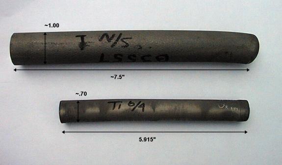
Figure 2 - Sintered sample
blanks as received
The extensional sound
velocity, c, was found from the sample dimensions and by measuring the
frequency of the first free-free flexural mode of vibration[9]
and the density obtained by measurement of displaced weight of water under
suspended immersion. Knowing both the
density and sound velocity permitted computation of Young’s modulus:
![]() (1)
(1)
where E is Young’s
modulus, r the density and c the
extensional sound velocity. For both
samples the density was found to be 4400 Kg/m3 (0.16 lbf/in3). The sound velocity for sample 1 was computed
from the flexural frequency to be 5100 m/s (200,000 in/s), while that for
sample 2 was 5300 m/s (210,000 in/s).
Hence the moduli:
Table 1
Density and Elastic
moduli for sintered samples
|
Sample |
Density, Kg/m3
(lbsf/in3) |
Modulus, GPa (Mpsi) |
|
1 (10 percent TiC) |
4400 (0.16) |
117 (17) |
|
2 (6-4) |
4400 (0.16) |
122 (18) |
To determine the mechanical
Q of these materials test specimens of Mason’s mass-spring-mass resonators[10],
also known as spool or dumb bell resonators, were machined from each. Figure 3 is a drawing of the powdered metal
specimens designed to resonate at 20 kHz.
Figure 3 – 20 kHz half
wavelength acoustic test specimen
The specimens were attached
to a 20 kHz transducer driven stepped horn as shown in Figure 4 using a
cyanoacrylate adhesive. The temperature
rise in the center of the stem, which is a motional node, was made using a
non-contacting infrared thermometer and confirmed by measurement using a Type K
thermocouple. The test duration varied
with the level of applied vibration[DW1].
Results
Table 2 provides a
representative sample of the raw data.
The resonant frequency for all tests and both specimens was measured to
be 19,990 Hz. The temperature measurements
shown are averages of at least three separate runs.
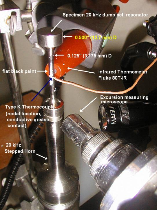
Figure 4 - Testing apparatus
arrangement
Table 2
20 kHz Typical Thermal Measurement Data
|
Specimen |
d,
microns (.001in) |
Duration, s |
DTav
,oC (oF) |
Computed
stress[11],
MPa (kpsi) |
Strain
% |
Comment |
|
2 |
64 (2.5) |
10 |
8.33 (15.0) |
260 (37) |
0.21 |
|
|
2 |
76 (3.0) |
10 |
11.9 (21.5) |
310 (44) |
0.24 |
|
Figure 5 is a representative
oscilloscope trace of the spindle temperature rise and fall during a single
test.
Figure 5 - Spindle temperature
variation with time
Figure 6 plots the Q, computed
using the measured values of temperature rise and stress according to Eq. (6b),
versus the strain. The specific heat, C,
of titanium was taken as 565 J/oK/kg (0.135 BTU/lb/oF =
1260 in.lbs/lb0F). It is
noted that Q’s computed without correction for heat loss were only ten percent
larger than the values shown.
Figure
6
The
specimen containing 10 percent TiC fractured from repeated operation at 310 MPa
cyclic stress. The 6-4 specimen
fractured when testing was attempted at 450 MPa.
Similar
measurements were also made on a test specimen made of the alloy 6Al-6V-2Sn
which was first annealed for one hour at 700 C (1300 F), followed by air
cooling. The pertinent material
properties, again obtained by measurement of the flexural vibration frequency
and density are tabulated below.
Table
3
Density and Elastic
moduli for 6Al-6V-2Sn sample
|
Density, Kg/m3
(lbsf/in3) |
Modulus, GPa (Mpsi) |
|
4510 (0.163) |
99.3 (14.4) |
A plot
of the Q of this sample versus operating cyclic stress is provided in Figure 7.
Figure 7
Although
this material exhibits a substantially lower Q than either of the sintered
6Al-4V samples, it was also tested for endurance at 414 Mpa (60 kpsi) operating
cyclic stress with the spindle cooled by a water spray as shown in Figure
8. The sample survived repeated 6
million-cycle operation at this stress level.
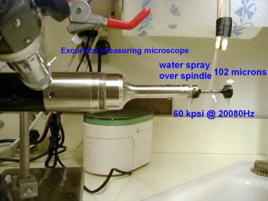
Figure 8 – Endurance
test of 6-6-2 Ti alloy
Test specimens
were also made for two samples made from 6Al-4V round bar stock, revealing a Q
of approximately 5000 at strains up to 0.33 percent. Annealing of these samples did not affect the Q.
A sample
of the 6-4 sintered material was also annealed at 730 C for one hour and
allowed to air cool. A specimen made
from this sample was also tested.
Annealing reduced the Q from the values shown in Figure 6 to those found
for standard rolled round stock.
As a
check upon the thermal method applied here, samples of 6-6-2 and 6-4 specimens
were cemented to an identically resonant transducer-booster combination whose
quiescent power consumption at a measured vibration amplitude was known. The additional power consumed at the same
amplitude with the specimen attached is due to losses in the specimen and the Q
can be computed by dividing the energy of vibration by the power lost per
cycle. The results obtained agreed with
those listed here within ten percent.
Discussion
While the values of Q measured
here are substantially below those found by Mason 3, all alloys evaluated appear comparable or superior
in performance to the venerable 6Al-4V titanium alloy.
The Q of sintered 6Al-4V Ti
appears to be substantially greater than that measured for cast and rolled
material, and indicates that the material is a promising substitute for use in
highly stressed ultrasonic horns as its acoustic losses begin to mount at the
same stress threshold of approximately 275 Mpa (40 kpsi) exhibited by the
conventional product. The alloy
containing 10 percent Titanium carbide and recommended for its ease in
machining, while exhibiting more modest performance and progressive degradation
at substantially lower dynamic stress, appears worthy of evaluation for use in
applications where the maximum dynamic stress does not exceed 200 Mpa (30
kpsi).
The 6-6-2 alloy exhibits about
the same losses as that shown in the samples made of common rolled 6-4 but it
appears capable of sustaining cyclic strains in the neighborhood of 0.4 percent
at 20 kHz in applications where cooling can be provided.
Acknowledgements
The author thanks Stanley
Abkowitz of Dynamet Technology for discussion of sintered products’ properties
and for supplying the samples and Professor Daniel Bershers of Columbia
University for advice regarding his own and W.P. Mason’s dynamic strain studies.
 , where f’' is the resonant frequency with mass